Saturday, 26 November 2016

Ultrasonic Distance Measurement using HC-sr04

Hiii Arduino Lovers,

In this post i am going to explain an introductory project on Distance Measurement with arduino & cheap Ultrasonic Ping Sensor HC-SR04.

Let's begin.

Things Required:

1) Arduino UNO

2) Ultrasonic Sensor Module - HC-sr04

3) LCD 16*2

4) Breadboard & Connecting Wires  

Introduction to Ultrasonic Sensor:

The HC-SR04 ultrasonic sensor uses sonar to determine distance to an object like bats or dolphins do. It offers excellent non-contact range detection with high accuracy and stable readings in an easy-to-use package. From 2cm to 400 cm or 1” to 13 feet. It operation is not affected by sunlight or black material like Sharp rangefinders are (although acoustically soft materials like cloth can be difficult to detect). It comes complete with ultrasonic transmitter and receiver module.

Specifications:
  • Power Supply :+5V DC
  • Quiescent Current : <2mA
  • Working Current: 15mA
  • Effectual Angle: <15°
  • Ranging Distance : 2cm – 400 cm/1" - 13ft
  • Resolution : 0.3 cm
  • Measuring Angle: 30 degree
  • Trigger Input Pulse width: 10uS
  • Dimension: 45mm x 20mm x 15mm 


Working:
To start measurement, Trig of SR04 must receive a pulse of high (5V) for at least 10us, this will initiate the sensor will transmit out 8 cycle of ultrasonic burst at 40kHz and wait for the reflected ultrasonic burst. When the sensor detected ultrasonic from receiver, it will set the Echo pin to high (5V) and delay for a period (width) which proportion to distance. To obtain the distance, measure the width (Ton) of Echo pin.
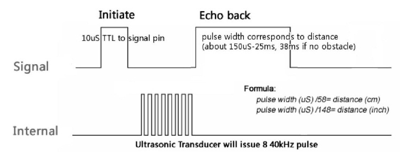


Calculation:
In arduino, we use pulseIn() funtion to calculate time. By using basic formula of speed which is

Speed = Distance
           Time

Now , Normal speed of sound is: 340.49 m / s 
And converting it to Centimeters per Micro Seconds gives : 0.034049 CM / microseconds

As distance traveled by pulse is twice the actual distance therefore Distance=2*(Actual Distance)
The actual distance traveled by the sound or the distance between the sensor and the object is:


0.034049 = 2*(Actual Distance)
                 Time

Actual Distance = (0.034049)*(Time/2) 

Circuit Diagram:
  
Code:

Result:


If you liked this article click on FOLLOW & don't forget to share. You can like us at: www.facebook.com/embdessol

Also view my other project's videos at: EmB DeS SoL's Channel

Friday, 25 November 2016

Introduction to ESP 8266 - 01

Hiii ESP Lovers,

Most of you have heard about Internet of Things (IoT) & ESP 8266. It's everywhere. Everywhere? Yes, Everywhere.

What it is?

In this post, I am going to explain ESP 8266 - 01. Let's go on a quick ride.


Intro:

The ESP8266 is perhaps the most versatile serial module to connect "things" at the Internet, that why it is so popular in the world of IoT.
 
It is a complete module, which includes a microprocessor which can be programmed directly via the Arduino IDE (C++), or in other environments to build (usually using a high level language itself, the "LUA").

 Have a look at ESP 8266 - 01

 
To control "things" there is no need to have the Arduino or other microcontroller itself to the interface because the ESP8266 has 2 GPIOs (two "pin" input / output).

Pin Description
  • VCC shall be connected to the 3.3V power supply
  • GPIO0 and GPIO2 are general purpose digital ports. GPIO0 also controls the module mode (programming or normal operation).
  • Rx: Receives Data (3.3 V logic Level)
  • CH_PD: Chip enable. Keep it on high (3.3V) for normal operation
  • RST: Reset. Keep it on high (3.3V) for normal operation. Put it on 0V to reset the chip.
  • GND is ground.
  • Tx: Transmits Data
 

Features
  • 802.11 b / g / n
  • Wi-Fi Direct (P2P), soft-AP
  • Integrated TCP / IP protocol stack
  • Integrated TR switch, balun, LNA, power amplifier and matching network
  • Integrated PLLs, regulators, DCXO and power management units
  • + 19.5dBm output power in 802.11b mode
  • Power down leakage current of <10uA
  • 1MB Flash Memory
  • Integrated low power 32-bit CPU Could be used the application processor
  • SDIO 1.1 / 2.0, SPI, UART STBC, 1 × 1 MIMO, MIMO 2 × 1
  • A-MPDU & A-MSDU aggregation & 0.4ms guard interval
  • Wake up and transmit packets in <2ms
  • Standby power consumption of <1.0mW (DTIM3) 
Hobbyist can use ESP at introductory level through AT Commands and Serial port (ex: Arduino IDE, Putty Terminal etc.) 

We'll cover AT Command test through arduino in our upcoming posts.

AT Commands


Applications:

ESP8266 can be used as an external Wifi module, using the standard AT Command set Firmware by connecting it to any microcontroller using the serial UART, or directly serve as a Wifi-enabled micro controller, by programming a new firmware using the provided SDK. 

The GPIO pins allow Analog and Digital IO, plus PWM, SPI, I2C, etc. 

This board has been used mostly in IoT contexts, where we want to add connectivity for example to an Arduino project. A wide adoption has been facilitated by the very modest price, ranging from 2.50 to 10 USD depending on the features offered by the manufacturers.
Some example projects:
  • Temperature logging and Web UI
  • Retro Web Browser
  • Let's tweet with ESP 8266

Hope you enjoyed this post, stay tuned for tutorials on ESP8266 which includes
  • Basic command test
  • Firmware flashing with Arduino
  • Temperature logger etc. 

Meanwhile you can take a look at my arduino projects videos at  EmB DeS SoL's Channel


Thursday, 24 November 2016

Atmega 328 and Atmega 8 pin Map

Atmega 328p and Atmega8 Pin Map

Hiii Arduino Lovers,

Below are the images of three most commonly used chips of AVR family i.e, Atmega 328, Atmega 168 and Atmega 8's pin mapping in arduino environment for programming reference.


a) Atmega 328 & 168's Pin Map :

  Note: Pin Mapping for Atmega 328 & Atmega 168 is roughly the same.


b)  Atmega 8's Pin Map :


Sunday, 20 November 2016

Tutorial 1: Bootloading Atmega 328p with USBasp programmer [Easiest]

 Bootloading Atmega 328p with USBasp Programmer [Easiest]


Hello arduino lovers,

The most common issue with Arduino is how to make a Standalone.

One way is to use your on board chip onto your standalone project but wait... why? 

When you can boot load your chip in less than 30 seconds with the help of USBasp programmer by setting only 4 fuse bits.

Let's begin.

List of Components

Hardware

1) Zero PCB or Breadboard

2) Atmega 328P

3) 16 MHz Crystal 

4) 22 pf capacitor

5) USBasp Programmer 

Software 

1) AVRDUDESS 2.4

2) Arduino IDE  

Tested on WIN 7 professional, AVRDUDESS 2.4 & Arduino 1.6.0. 

Step 1: Setting up connections

Follow circuit below


 Add 16MHz crystal alongwith 22pf capacitors. Sorry, lazy enough to draw.

Results: Don't confuse about pin base i used 40 pin becoz that's available at the moment.


Step 2: Setting up fuse bits.

After making connections as per circuit, its time to set fuse bits to your Atmega328.

Caution : Implement this step with full attention, writing wrong fuse bits might kill your chip.

Open AVRDUDESS and follow below figures

Figure 1: Select programmer USBasp


Figure 2: Detect your chip version, if connections are ok it'll automatically detect your chip


Figure 3: Writing fuse bits. 
Note that chip comes with default fuse bits as (yours may vary)
L- 0x62
H - 0xD9
E - 0x07
L - 0xFF


Replace these fuse bits with the following
L - 0xFF
H - 0xDE
E - 0x05
LB - 0x3F    
and tick set fuse option and then click write as shown

 
 Voila! You have successfully written fuse bits.

Step 3: Burning the beast oh! sorry Boot loader.

Choose the path as shown in figure.


 After choosing path from AVRDUDESS, click on program button as shown.


Wait for some time say 10-20 seconds until logs will cease to come in black area. That's it.

You have successfully loaded boot loader into Atmega 328 p. You can use it as standalone or as a replacement in Arduino board.

Hope, you liked this article. Don't forget to share.

Take a look at video tutorial
https://www.youtube.com/watch?v=nh3h9gwOF4Q