Hiii Arduino Lovers,
In this post i am going to explain an introductory project on Distance Measurement with arduino & cheap Ultrasonic Ping Sensor HC-SR04.
Let's begin.
Things Required:
1) Arduino UNO
2) Ultrasonic Sensor Module - HC-sr04
3) LCD 16*2
4) Breadboard & Connecting Wires
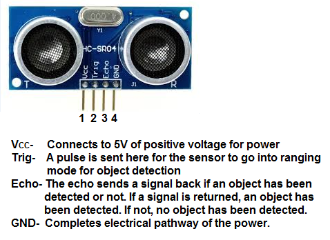
Introduction to Ultrasonic Sensor:
The HC-SR04 ultrasonic sensor uses sonar to determine distance to an object like bats or dolphins do. It offers excellent non-contact range detection with high accuracy and stable readings in an easy-to-use package. From 2cm to 400 cm or 1” to 13 feet. It operation is not affected by sunlight or black material like Sharp rangefinders are (although acoustically soft materials like cloth can be difficult to detect). It comes complete with ultrasonic transmitter and receiver module.
Specifications:
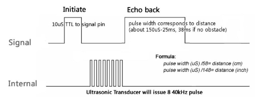
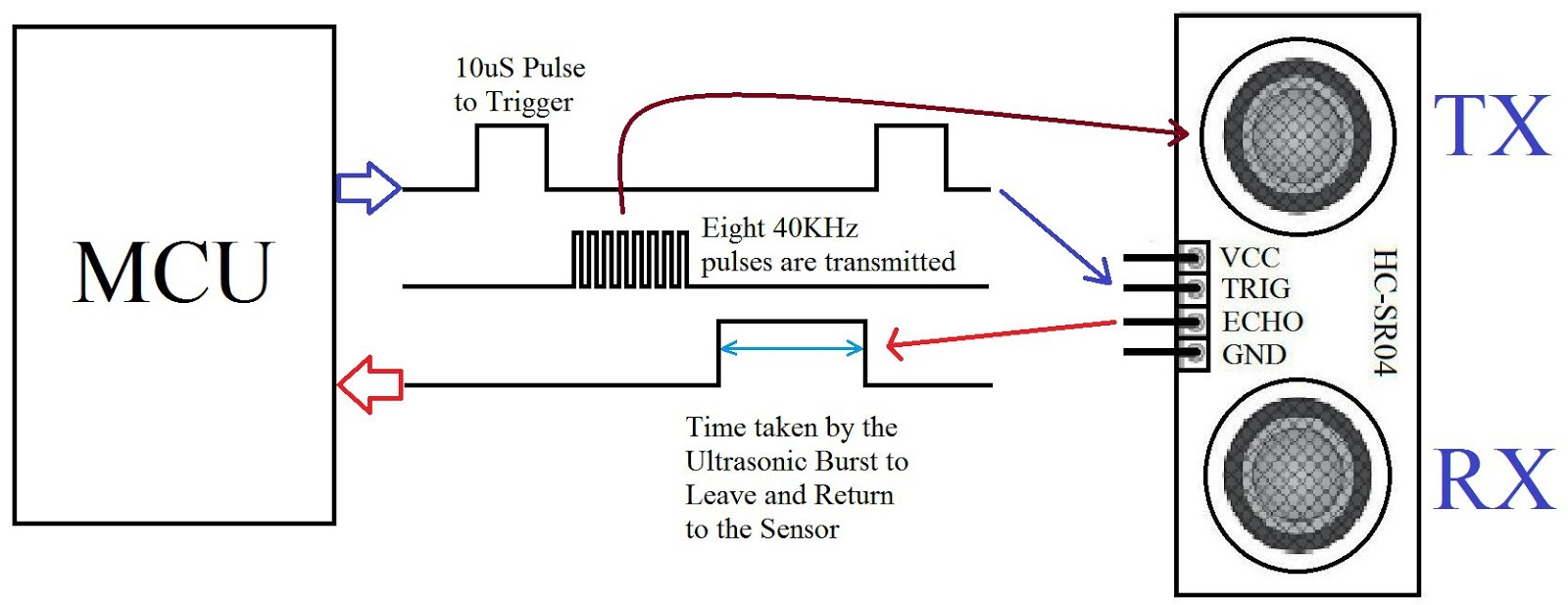
Working:
To start measurement, Trig of SR04 must receive a pulse of high (5V) for at least 10us, this will initiate the sensor will transmit out 8 cycle of ultrasonic burst at 40kHz and wait for the reflected ultrasonic burst. When the sensor detected ultrasonic from receiver, it will set the Echo pin to high (5V) and delay for a period (width) which proportion to distance. To obtain the distance, measure the width (Ton) of Echo pin.

Calculation:
In arduino, we use pulseIn() funtion to calculate time. By using basic formula of speed which is
Now , Normal speed of sound is: 340.49 m / s
And converting it to Centimeters per Micro Seconds gives : 0.034049 CM / microseconds
As distance traveled by pulse is twice the actual distance therefore Distance=2*(Actual Distance)
The actual distance traveled by the sound or the distance between the sensor and the object is:

 If you liked this article click on FOLLOW & don't forget to share. You can like us at: www.facebook.com/embdessol
Also view my other project's videos at: EmB DeS SoL's Channel
In this post i am going to explain an introductory project on Distance Measurement with arduino & cheap Ultrasonic Ping Sensor HC-SR04.
Let's begin.
Things Required:
1) Arduino UNO
2) Ultrasonic Sensor Module - HC-sr04
3) LCD 16*2
4) Breadboard & Connecting Wires
Introduction to Ultrasonic Sensor:
The HC-SR04 ultrasonic sensor uses sonar to determine distance to an object like bats or dolphins do. It offers excellent non-contact range detection with high accuracy and stable readings in an easy-to-use package. From 2cm to 400 cm or 1” to 13 feet. It operation is not affected by sunlight or black material like Sharp rangefinders are (although acoustically soft materials like cloth can be difficult to detect). It comes complete with ultrasonic transmitter and receiver module.
Specifications:
- Power Supply :+5V DC
- Quiescent Current : <2mA
- Working Current: 15mA
- Effectual Angle: <15°
- Ranging Distance : 2cm – 400 cm/1" - 13ft
- Resolution : 0.3 cm
- Measuring Angle: 30 degree
- Trigger Input Pulse width: 10uS
- Dimension: 45mm x 20mm x 15mm
Working:
To start measurement, Trig of SR04 must receive a pulse of high (5V) for at least 10us, this will initiate the sensor will transmit out 8 cycle of ultrasonic burst at 40kHz and wait for the reflected ultrasonic burst. When the sensor detected ultrasonic from receiver, it will set the Echo pin to high (5V) and delay for a period (width) which proportion to distance. To obtain the distance, measure the width (Ton) of Echo pin.
Calculation:
In arduino, we use pulseIn() funtion to calculate time. By using basic formula of speed which is
Speed = Distance
Time
And converting it to Centimeters per Micro Seconds gives : 0.034049 CM / microseconds
As distance traveled by pulse is twice the actual distance therefore Distance=2*(Actual Distance)
The actual distance traveled by the sound or the distance between the sensor and the object is:
0.034049 = 2*(Actual Distance)
Time
Actual Distance = (0.034049)*(Time/2)
Circuit Diagram:

Code:
Result:

Also view my other project's videos at: EmB DeS SoL's Channel